.......................................
Transcranial Magnetic Stimulation (TMS)
.......................................
================================
INTRODUCTION
================================
Assembly of this device was partially funded by people who have been following my build progress on reddit, who have preordered a future, more advanced version. Thanks to them, I'm able to work toward making rTMS therapy available for less than its current, nosebleed-inducing $15000 price tag. Every neurostimulation design I finish goes straight to the public domain!
DISCLAIMER: THE DEVICE DESCRIBED HERE IS THE MOST DANGEROUS THING TO BUILD THAT I HAVE POSTED INSTRUCTIONS FOR SO FAR. LARGE CAPACITORS ARE HELD AT MORE THAN A THOUSAND VOLTS, AND THE DEVICE RUNS ON A MODIFIED MICROWAVE OVEN TRANSFORMER WITH A SECONDARY VOLTAGE OF SEVERAL THOUSAND VOLTS. TOUCHING THE DEVICE WRONG DURING ASSEMBLY CAN INSTANTLY KILL YOU. THIS DEVICE COULD KILL YOU OR MAIM YOU OR BREAK YOUR MIND. HIGH VOLTAGE HAZARD. MAY CAUSE SEIZURES.
WHEN PROPERLY ASSEMBLED AND USED (TMS RISKS FROM WIKIPEDIA): The greatest immediate risk is the rare occurrence of syncope (fainting) and even less commonly, induced seizures. Other adverse short-term effects of TMS include discomfort or pain, transient induction of hypomania, transient cognitive changes, transient hearing loss, transient impairment of working memory, and induced currents in electrical circuits in implanted devices.
---
I began designing the device described here intending to build a machine to duplicate the procedures of clinical rTMS (repetitive transcranial magnetic stimulation), which is used to treat depression, among other applications. However, this machine is only on par with the MAGSTIM 2002 in terms of its performance envelope. The maximum rate of output pulsing this device can achieve is only a pulse every few seconds, not the dozens of pulses per second needed for rTMS. More work on a different design will be required to make an open-source machine capable of true rTMS.
Long story short, this is a TMS device, but not an rTMS device; rTMS will come in a later design iteration. More or less every component in this design is being abused but it's cheap for what it is and it passes tests, so I'm releasing the design even though these units will probably fail fairly quickly once built and used. This device should be good enough for a couple studies or a treatment course.
If you're here looking for a device you can build yourself to treat your depression, check out tDCS, which is easier to make as a first electronics project, and safer to work with. You can also buy tDCS devices on eBay for ~$30 shipped, as of the time of this writing.
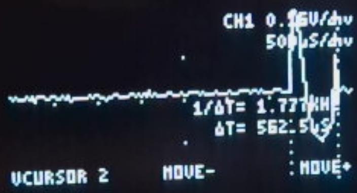
Key numbers:
$614.01 COST IN PARTS
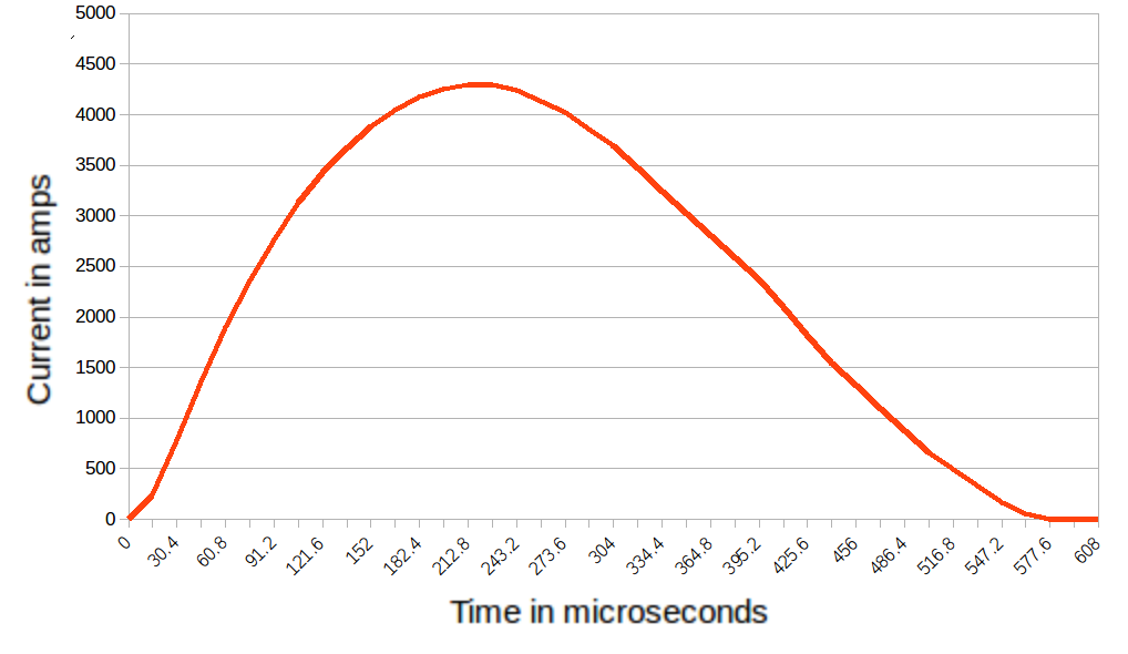
562.5 MICROSECOND PULSE DURATION
4250 AMP PEAK PULSE CURRENT
3.95 SECONDS BETWEEN PULSES AT 800V CHARGE
================================
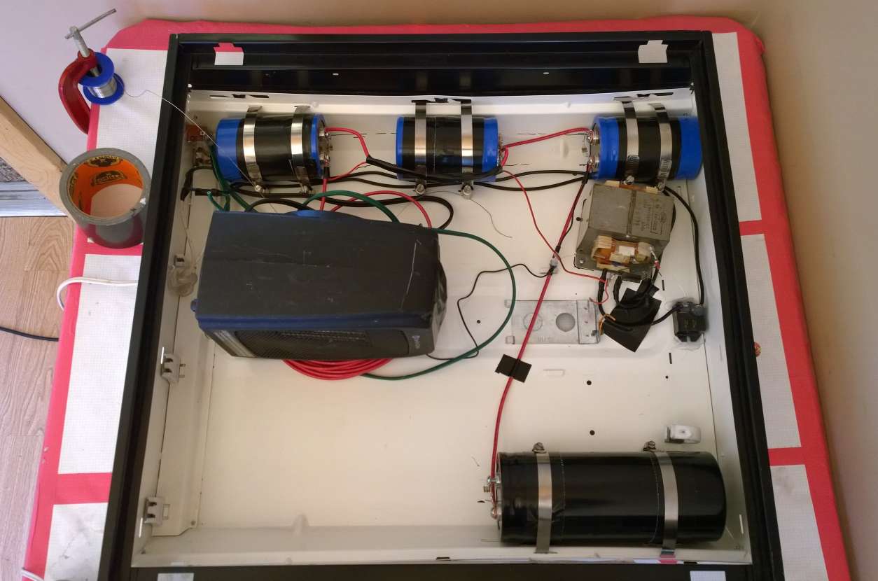
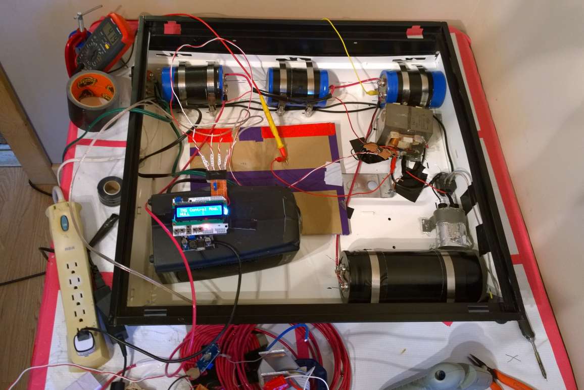
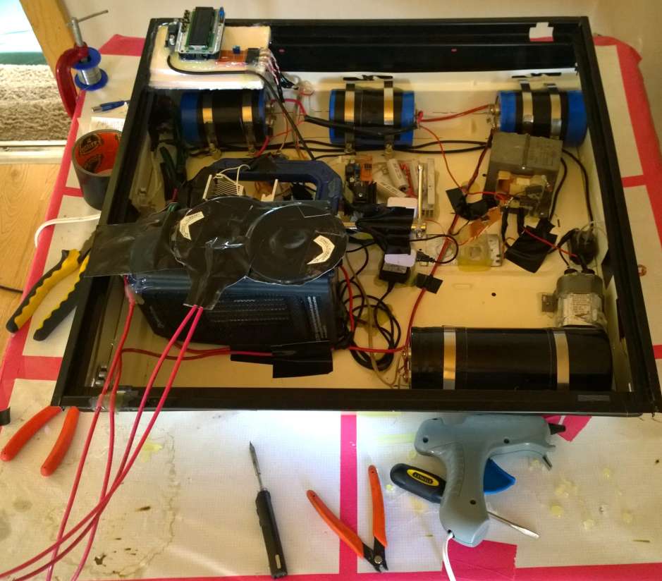
PROTOTYPING PICTURES
================================
Many innocent parts were fried to reach a working model.
================================
PRACTICAL ASSEMBLY
================================
IS IT PLUGGED IN? NO? GOOD! DO NOT PLUG IN UNTIL LATER! YOU TOUCH WRONG, YOU DIE!
DO NOT PLUG IN UNTIL LATER!
TOUCH WRONG = CARDIAC ARREST + 'POP' SOUND + DIM FLASH OF LIGHT + DEATH
_DO_NOT_PLUG_IN_UNTIL_LATER_
That said, the build process is as follows:
Parts list and schematic (as .zip)
Mount the power switch to the enclosure with its solder tabs facing inward.
Run the input power cable through a hole in the enclosure. Tie a knot in the input power cable on the inside of the enclosure. Use hot glue to secure the knot flush against the inside of the enclosure, creating a cable strain relief. Connect the "hot" side of the input power cable to the power switch, and attach another wire leading out from the power switch, which will carry the switched "hot" line.
Create 4 1Watt 250kOhm resistors by soldering together 4 groups of 4 resistors in parallel, using 16 (common) 1MOhm 250mW resistors.
Note where the capacitors will be mounted on the enclosure. Note where slots need to be cut for hose clamps and where the capacitors touch the enclosure's surface. Mark with permanent marker. Place blobs of hot glue where the capacitors will touch the enclosure, these will provide grippy, padded surfaces the hose clamps can press the capacitors against to firmly mechanically mount them.
Next you'll need to bounce around between two tasks: attaching wires and bleed resistors to the capacitor terminals and mounting the capacitors in the enclosure. In my device, the capacitors are mounted such that you can't really get to the terminals to screw on wires once all the capacitors are in the enclosure. For wire, I used 10AWG (5,26mm^2) copper stranded. Rated for 600V, used at about double its rated voltage but it'll probably be fine...
MAKE SURE EVERY CAPACITOR HAS A BLEED RESISTOR IN PARALLEL WITH IT OR YOU MIGHT DIE WHILE TROUBLESHOOTING LATER
To attach the capacitors to the enclosure, place the capacitors against the blobs of hot glue and run stainless steel hose clamps through slots encircling the capacitor, two hose clamps per capacitor. Put gorilla tape around the side of the capacitor that the hose clamps touch and tighten the hose clamps until they start to slightly press into the gorilla tape.
The three smaller capacitors, 4700uF 450V, are wired in series. The positive output of this series chain goes to a long length of wire, which will later be formed into the TMS coil. The negative of this chain is wired to the negative of the giant capacitor, 18000uF 400V. The positive and negative of the three-capacitor series chain must also have smaller wires that go from them to the charge circuit (microwave oven transformer and diodes).
To prepare the microwave oven transformer, cut off the low-voltage output windings, cut the high-voltage output winding's connection to the transformer core, and carefully scrape along one of the wires halfway in the middle of the high-voltage output winding. Tin the scraped area with solder, strip and tin some fine magnet wire, and use the soldering iron to melt the magnet wire into the scraped and tinned wire of the transformer's high-voltage output, making it center-tapped.
To prepare the space heater (I used model # CZ442WM), cut the fan power wires and attach longer wires to them, running out of the heater, and to the switched "hot" wire and the input "neutral" wire. This will ensure the fan gets full power even though the rest of the space heater is used as a giant (cheap) load resistor. Bypass the tilt detection switch on the space heater (on my model you could just pull out a microswitch and solder its wires together). They say "if it's stupid, but it works, it ain't stupid, 'cuz it works". My first two power supply designs for this thing catastrophically failed, and simplifying things down and adding some hacky fixes improved the performance dramatically.
Now we can connect more of the main capacitor charge circuit.
Wire the space heater's factory input power cord from the switched "hot" wire of the main power switch to one of the N.O. contacts of the relay. Wire the other N.O. relay contact to the microwave oven transformer's 120VAC input. Wire the free end of the microwave oven transformer's 120VAC input to the "neutral" wire of the main input power cord. Closing the relay will now power up the microwave oven transformer's 120VAC input line, but the space heater heating assembly will limit the power that the microwave oven transformer can draw. Even if the transformer's output looks like a short circuit, the space heater will prevent the drawn power from exceeding 1500W (actually a lower value, this is theoretical maximum with the transformer acting as a pure short-circuit).
Wire the 0.94uF 2000V capacitor (or other, similar value obtained from the salvage microwave oven; just make sure it's not short-circuited) across the microwave oven transformer's 120VAC input. The capacitor suppresses the voltage spikes opening the relay otherwise creates. It also introduces ringing, but that won't be a problem for us here.
Now we can work on the microwave oven transformer's output. Oh, and by the way, did I mention...
IS IT PLUGGED IN? NO? GOOD! DO NOT PLUG IN UNTIL LATER! YOU TOUCH WRONG, YOU DIE!
The center-tap on the microwave oven transformer's high-voltage output lead, the wire you soldered on, must be wired to the negative terminal of the three-capacitor series chain. The two free ends of the microwave oven transformer's high-voltage output winding go to the anodes of two HVR-1X-4 diodes (easily scavenged from old microwaves), whose cathodes are then connected together and wired to the positive terminal of the three-capacitor series chain.
The rest of the circuit is wired according to the schematic included with the bill of materials. Your physical layout will probably differ from mine.
Here is the test firmware, a .ino file. NOTE THAT THE TEST FIRMWARE DOES NOT LIMIT THE CHARGE VOLTAGE, YOU CAN HOLD DOWN THE CHARGE BUTTON UNTIL THE CAPACITORS EXPLODE! Let off the button when the voltage is 1200V to prevent that from happening.
================================
WINDING THE COIL
================================
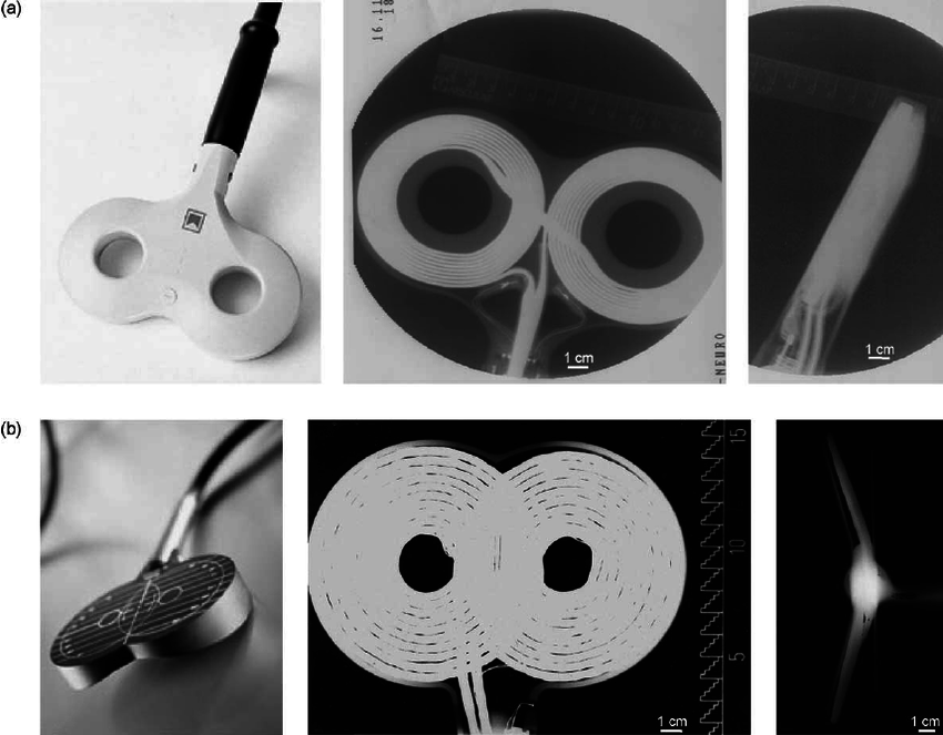
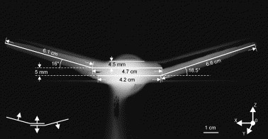
Some commercial TMS coils
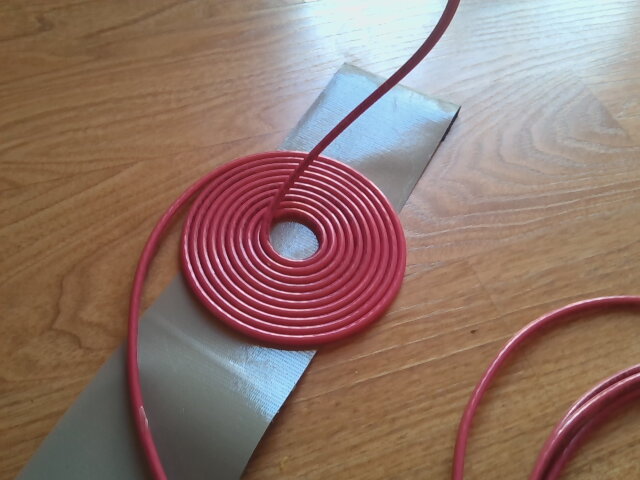
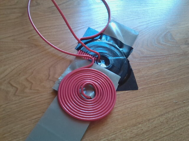
My own coil winding (using gorilla tape as a backing to keep the windings neat)
================================
HELP FROM THE INTERNET
================================
During the design phase, I got one snippet of help from the internet, which led me to reduce the size of the main capacitor significantly, from 18millifarads to 1.56millifarads. Here is the conversation in its entirety:
[-]bf2017 1 point 11 days ago*
While your TMS machine design is operating in the right area for pulse energy I'm not so sure about the pulse period. Using the 16.35uH butterfly coil and your specified 20000uF capacitor, the resonant period is 3.59msec. A professional machine like the MagStim Rapid 2 operates with a pulse period of ~400usec. This faster period gives a higher di/dt and rate of change of flux which allows for effective induction of potential into neurons.
In order to bring the pulse period down a smaller capacitance is required. With a 16.35uH coil your looking at 248uF or less. After much reading on magstim models (i would love to open one up for inspection) I believe they use a capacitance around 200uF.
This is where things get complicated and expensive. In order to increase energy with the smaller capacitance, the operating voltage must be increased. I have read in magstim manuals that the maximum operating voltage is 2.6kV. For your example of 7000A pk you would need a stored charge of 2000V in a 200uF cap. Now were talking SCRs with blocking voltages > 2000V and high surge capabilities which are not cheap. Also simple charging circuitry is out due to the operating voltage and time constraints when operating at higher frequencies.
Also note that at higher pulse speeds the turn-off time of the semiconductors becomes critical. My current design for the semiconductor switch utilizes an inverter grade puck SCR and fast diode connected inverse parallel. I had a slower 'line frequency' rated diode previously and that was fried after several test fires. Essentially after one resonant period the diode couldn't re-establish blocking voltage and conducted a second pulse in reverse, leading to instant death of the diode.
I am all for increasing the availability of TMS after watching family members struggle with severe depression and seeing how effective it is at reversing the symptoms. We're currently paying $5000 for a single course (1 month) of treatment for my father in law. I have been researching and designing a TMS machine in my spare time over the last year using the magstim machine specs as a guideline. While it can be done and for less cost than a professional machine, I think that it may not be this simple.
Edit:
Actually if you have two 20000uF capacitors with the inductor in between the total capacitance is halved during conduction so the resonant period ends up at ~1.8msec.
[-]quicksilv3rflash[S] 1 point 6 days ago
I've got two VS-ST730C16L0 thyristors, but they top out at 1600V. And of course it's inadvisable to run them at exactly their rated absolute maximum voltage rating. It's rather... difficult to get 2000v 200uF capacitors with my current budget to finish the device ($180). After completing this design I will see about refining it to match the shorter discharge period of the commercial tech. However, since my neurons have a max frequency of 150Hz, the shortest period they perceive must be around 6.7 milliseconds, no? Do 400us pulses and 1800us pulses actually affect the brain differently? I mean that last question seriously, not critically, if you can find any research on the effects of different pulse durations I would like to read them to see how important narrowing the pulse period is. First off, though, I need to get the thing pulsing and properly cooled at all. Especially if I need to ask the internet for money for crazy expensive doorknob laser capacitors, I need to have a working prototype to show so they know I'm not just trying to take their money.
Thank you for your interest, -V
[-]bf2017 1 point 3 days ago*
Its correct that neurons are operating at a lower frequency. This is why the stimulation pulses are typically done in 10 - 20 Hz pulse trains.
The trick is that each individual pulse needs to have a fast rise in current (di/dt) & magnetic field (dB/dt) in order to generate a sufficient electric field in the brain to fire neurons. Since the machine is essentially a LCR oscillator, the resonant period needs to be short (smaller C and L) so the current has a high dI/dt.
I found this paper pretty informative:
https://www.researchgate.net/publication/12455080_Transcranial_magnetic_stimulation_-_A_new_tool_for_functional_imaging_of_the_brain
Specifically for this topic we're discussing read from the section: Electromagnetic Theory of TMS: Basic Principles and the following paragraphs and later on from IV Instrumentation: Stimulus pulse generation which explains some of the internal workings.
I don't know for certain what the minimum required pulse is but I've read in MagStims literature up to 1msec. Though I don't know if thats monophasic or biphasic. The difference being that monophasic typically has a fast front edge and long tail as current decays. Biphasic is sinusoidal and with a period between 200uSec and 400 uSec in the material I've read.
Also, on the topic of capacitors. I dont know how well electrolytics would be at tolerating repeated high discharges. They're mostly for power supply filtering and only see comparatively small amounts of current ripple. They can probably handle a few large discharges at a reduced lifespan. I'm using a bank of 24 46uF 600Vac/1000Vdc metal films that I picked up on ebay a few years ago for cheap. They're not ideal but they can handle the full AC. Ideally it should be a "pulse" capacitor but they will be pricey. There are some suppliers on alibaba that I've been looking at, though I dont know what the quality is like.
================================
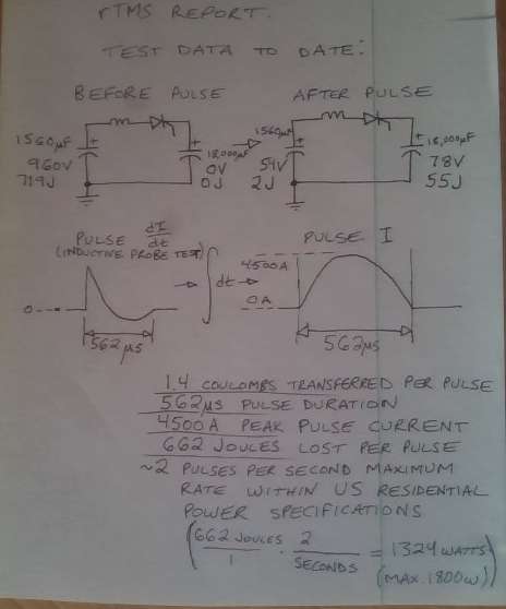
DEVICE TEST RESULTS
================================
================================
MADNESS
================================
Repetitive transcranial magnetic stimulation (rTMS) is an FDA-approved treatment for depression. However, in the United States at least, rTMS is not available to many patients due to the exorbitant fees (~$15,000!) imposed by the gatekeepers of our medical system for access to a chance to feel happiness again. That's extortion.
Luckily, building and possessing transcranial stimulation hardware is not yet regulated by U.S. law, so I'm attempting to leverage this absence of regulation to the maximum extent possible by releasing open-source designs of transcranial stimulation devices into the public domain. So far I've finished tDCS, tACS, 2-channel tACS, and with these instructions, TMS. Having secured all of my own physical needs, I do not have any purpose in existence beyond attempting to shape the world to match my own personal conception of ethics. Many entities are attempting to do this, and whoever has the most rapidly unfolding plan will likely be the victor.
I'm angling for some sort of eco-communist brainwashing cult -- I mean family -- with the final aim of fusing the minds of as many perceptive entities as can be voluntarily recruited, by using a combination of nootropic drugs, transcranial electrical stimulation, and transcranial magnetic stimulation to rewrite the personalities of myself and the volunteers in order to convert us to blissed-out altruist super-soldiers to save the world.