.......................................
Two Channel Transcranial Alternating Current Stimulation
.......................................
================================
INTRODUCTION
================================
This device was constructed as a result of the sponsorship of reddit user /u/nzt49.
The instructable here is an extension of my previous work, "Transcranial Electrical Stimulator, Arduino Compatible", and uses two copies of the previously designed circuit board in order to produce a two-channel transcranial electrical stimulator. This device's code can be readily modified to provide arbitrary dual-channel stimulation outputs. With the code provided here, this stimulator will enable you to replicate the stimulation montages of the following studies:
Alekseichuk, Ivan, et al. "Spatial Working Memory in Humans Depends on Theta and High Gamma Synchronization in the Prefrontal Cortex."
" Cell: Current Biology, vol. 26, no. 12, 26 May 2016, pp. 1513-1521., doi:10.1016/j.cub.2016.04.035.
Neubauer, A. C., et al. "The influence of transcranial alternating current stimulation (TACS) on fluid intelligence: An fMRI study." Personality and Individual Differences, Pergamon, 4 Aug. 2017,
sciencedirect.com/science/article/pii/S0191886917302660.
Violante, Ines R., et al. "Externally
induced frontoparietal synchronization modulates network dynamics and
enhances working memory performance." eLife, Imperial College
London, 14 Mar. 2017;6:e22001
doi: 10.7554/eLife.22001.
----------------------------------------------------------------------------
DISCLAIMER: The device here, if improperly constructed, can cause bodily harm ranging from headache to seizures to death. If correctly constructed, this device may still cause seizures in susceptible individuals, and it operates by changing the user's mind in a manner that may be permanent. The user may find these potentially permanent neurological changes to be undesirable, and users must be aware of, and willfully accept, this risk. The Croatian Medical Journal has published a paper claiming that it's unethical to release instructions like this (my design is citation #10), but since I am otherwise a puny human, and in this specific field I have an asymmetrical advantage vs. constraining institutions, I seek to press forward. All this mind control technology can probably be abused in profoundly disturbing ways; I am uncertain that its existence is a clearly good thing, but since the genie is already out of the bottle ... I would rather that everyone have access to these tools instead of only centralized institutions.
================================
DESIGN REQUIREMENTS
================================

Extracted and reorganized by stimulation type from the methods of the papers listed in the introduction,
"Spatial Working Memory in Humans Depends on Theta and High Gamma Synchronization in the Prefrontal Cortex" ;
"Externally induced frontoparietal synchronization modulates network dynamics and enhances working memory performance" ;
"The influence of transcranial alternating current stimulation (tACS) on fluid intelligence: An fMRI study"
----------------------------------------------------------------------------
Single channel modes: some of the stimulation montages only use a single channel. To support these stimulation montages, only a simple constant-current AC output is required, at the frequencies 5Hz and 6Hz, with an intensity of 1mA or 1.5mA.
---
Single-Frequency Alternating Current Stimulation: SF-6
A continuous, sinusoidal 6 Hz stimulation was applied at an intensity of 1 mA peak to baseline.
---
Single-channel theta frequency (5Hz) stimulation
Stimulation
waveform was sinusoidal without DC offset and a 0 degree relative phase.
The impedance level was kept below 10 kOhm throughout the entire
stimulation period. The applied oscillating currents corresponded to
mean theta frequency in previous studies (Jacobson, Goren, Lavidor, &
Levy, 2012; 5 Hz); current intensity was 1500 μA.
----------------------------------------------------------------------------
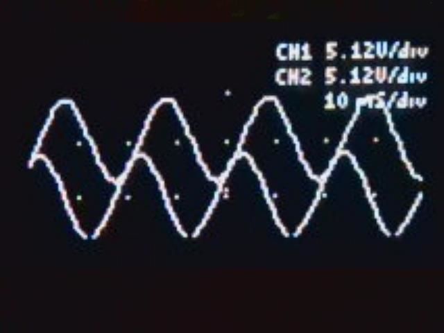
Multichannel modes with one channel modulated by the other: the 'cross-frequency' stimulation uses one underlying low-frequency sine wave at 6Hz and another high-frequency sine wave at 40Hz-200Hz, with the high-frequency wave only being present during either the positive half-cycle or the negative half-cycle of the low-frequency wave.
---
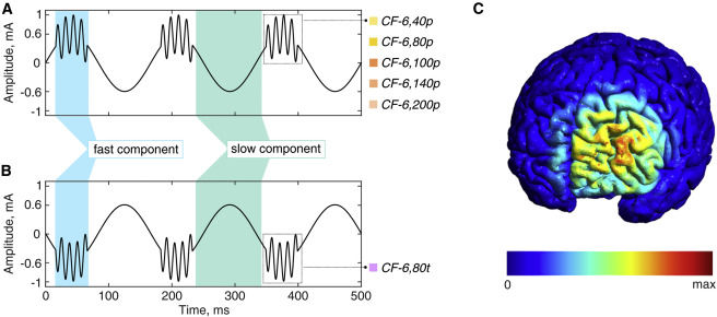
Cross-Frequency Alternating Current Stimulation: CF-"Theta-Gamma Frequencies"
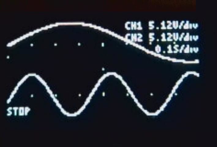
This stimulation consisted of two superimposed components: continuous slow wave, and repetitive bursts of fast oscillations. The slow component was the 6 Hz sinusoidal stimulation with 0.6-mA peak-to-baseline current for every corresponding condition. The fast component frequency was 40 Hz (condition CF-6,40t), 80 Hz (CF-6,80t and CF-6,80p), 100 Hz (CF-6,100p), 140 Hz (CF-6,140p), or 200 Hz (CF-6,200p) at 0.4 mA peak to baseline. Bursts were synchronized with the continuous wave and lasted for 50 ms during every trough (CF-6,80t) or peak (CF-6,40p, CF-6,80p, CF-6,100p, CF-6,140p, and CF-6,200p). Temporally accurate fusing of the components was achieved by dedicated hardware and monitored with an oscilloscope.
----------------------------------------------------------------------------
Bursts mode
---
Gamma-Burst Stimulation: Bursts
Bursts of 80 Hz alternating current were applied for 50 ms six times per s with a current of 0.4 mA peak to baseline with positive or negative DC offset (Bursts+ or Bursts-). Total intensity was equal to 1 mA peak to baseline. These stimulation conditions were designed to reproduce the conditions CF-6,80t and CF-6,80p without the continuous slow-wave component.
----------------------------------------------------------------------------
Multichannel modes with a specific phase relationship between the two channels:
---
In- and anti-phase theta frequency (6 Hz) stimulation
Stimulation was sinusoidal, 6 Hz frequency, peak-to-peak amplitude of 1000 μA, and no DC offset.
TACS was delivered in two different conditions: (1) Synchronous condition (0 degree) - Electrodes F4 and P4 with a 0 degree phase offset and return electrode at T8; (2) Desynchronous condition (180 degree) - same montage as in the 'synchronous' condition, but electrodes F4 and P4 had a 180degree phase offset.
================================
PARTS LIST
================================

{{{{ Total cost: $162.96 }}}}
(prices as of early 2017)
$27.89 // printed circuit boards
$51.33 // board components
$12.96 // device power components
$34.78 // human input components
$36.00 // Arduino Uno / lcd+keypad
--------------------------------------------------------
Section 1: Components to populate the board (Total: $51.33, prices as of 2017-01-15, subtotal $46.34, $4.99 economy shipping)
--------------------------------------------------------
These parts are available from Mouser or Digikey, among others. Get extras of the cheap ones if you suspect a tweezer mishap may send a tiny piece irrevocably flying off into shag carpeting... or you'll have to wait another week and pay double shipping. If you're feeling skilled, careful, and/or lucky, order exactly the required number of each piece.
$0.19/ea. 2x LG Q396-PS-35
$0.21/ea. 2x 150120AS75000
$0.55/ea. 6x FMMT734TA
$0.55/ea. 6x FMMT634TA
$1.03/ea. 2x ADR5041BKSZ-REEL7 (if out of stock, substitute ADR5041BKSZ-R2 at $1.41/ea.)
$0.10/ea. 12x CRCW060375K0FKEA
$0.09/ea. 4x ERJ-3GEYJ363V
$1.37/ea. 4x RG1608N-102-P-T1
$0.63/ea. 2x ERA-3AEB86R6V
$0.10/ea. 4x CRCW06037K15FKEA
$1.61/ea. 4x TLC2252CDR
$0.67/ea. 4x LM4040D10IDBZR
$2.98/ea. 2x REF5050AIDR (if out of stock, substitute REF5050AQDRQ1 at $3.51/ea.)
$0.39/ea. 2x L78L05ACD13TR
$2.76/ea. 2x SI8630BD-B-IS
$2.52/ea. 2x DAC7311IDCKR (if out of stock, substitute DAC7311IDCKT at $2.74/ea.)
$0.10/ea. 4x 35202K2JT
$0.17/ea. 8x GRM188R61H105KAALD
==================================
Section 2: the board itself (Total: $27.89 minimum, price as of 2017-01-19, SHIPPING RATES WILL VARY OVER TIME, $9.90 subtotal + $17.99 cheapest shipping)
--------------------------------------------------------
The .zip file provided is compiled for SeeedStudio Fusion PCB specifically! You'll need to go to the github repository [LINK TO ASSOCIATED GITHUB REPOSITORY] to get the actual .brd files and reprocess them if you need gerbers (PCB design files) for a different manufacturing service. I'm only giving instructions for purchasing though Seeed here because they're the service I used for the tested prototypes, and also the cheapest I've found that doesn't noticeably cut quality.
Ordering instructions:
You'll be ordering from SeeedStudio Fusion PCB. These people have a two-week maximum manufacturing turnaround time but a really slow shipping carrier. After making an account with SeeedStudio (sorry), you need to submit a set of gerber files to be manufactured, packaged in a .zip. I've already assembled the .zip for you, it's embedded at the bottom this step, seeed_fusionpcb_gerber.zip. Download it. This .zip file is also on github. On the order page linked, click the button labeled "Add your gerber file", browse to your downloaded copy of seeed_fusionpcb_gerber.zip, and upload it. Select the following options:
MATERIAL: FR4-TG130 (or whatever says FR4 as the first three characters)
LAYERS: 2 LAYERS DIMENSIONS: (manually enter or click the blue autofill measurements to the right of "DIMENSIONS") 56.5 * 56.5 (mm)
PCB QTY: 10 (might as well, there's no price break for 5...)
PANELIZED PCBS: 1
PCB THICKNESS: 1.6 (mm)
PCB COLOR: GREEN (you can choose a different one but they charge more)
SURFACE FINISH: HASL
COPPER WEIGHT: 1 OZ.
MIN HOLE SIZE: 0.3mm
MIN TRACKING/SPACING: 6/6 mil
BLIND VIAS: NO
HALF-CUT/CASTELLATED HOLES: NO
IMPEDANCE CONTROL: NO
...then click "add to cart", and then the little cart icon in the top-right, and then it's a standard online retailer checkout. It's highly recommended to get expedited shipping. (Isn't ordering boards fun? Look at all the miscellaneous units up there! Ounces (per square foot, implicitly), millimeters, mils... why choose between the imperial and metric system when you could make an even more convoluted global standard setup that drags in units from both?)
===============================
Section 3: device power components (Total: $12.96, from various suppliers around ebay as of 2017-01-18) These device power supply components are standard blocks that have been cloned by multiple suppliers. They're cheap, common, identical from multiple manufacturers and sellers, and they appear reliable (never had one break yet), but I can't find the "proper" names and model numbers for them. So I recommend simply searching for the quoted phrases below on eBay.
--------------------------------------------------------
$1.68/ea. 2x "DC 3-32V Step Up to 5-35V Boost Converter Voltage Regulator Power Supply Module"
$1.68/ea. 1x "LM2596 Buck Module"
$0.99/ea. 2x "Mini DC2.5-30V LED Panel Voltage Meter 3-Digital Display Voltmeter"
$0.99/ea. 3x "Holder Case For 4AA (6V) With Wire Leads Plastic Battery Storage Box"
$0.99/ea. 3x "DPDT ON/ON Toggle Switch"
===============================
Section 4: human input components (Total: $34.78, from various suppliers around ebay as of 2017-01-18) The searches linked in this section should pull up 2mm pin connector leads and 2mm pin compatible sponge electrodes. IF YOU WANT TO USE "AMREX" STYLE SPONGE ELECTRODES YOU NEED "BANANA PLUG" LEADS INSTEAD OF 2mm PIN LEADS!
--------------------------------------------------------
$15.50/ea. 2x "tDCS Dual Electrodes bundle: Sponge (1pair) & Self-Adhering (2pair)"
$01.89/ea. 2x "Standard Electrode Lead Wires Standard Pin Connection For Tens / Ems Machines"
===============================
Section 5: data input components (Total: $36.00, from various suppliers around ebay as of 2017-11-18)
--------------------------------------------------------
$18.00/ea. 1x "Arduino Uno and USB cable"
$18.00/ea. 1x "Velleman VMA203 LCD/keypad shield"**
**this shield comes in two revisions with different button sense thresholds required for each. If the buttons don't seem to work right, this is the most likely cause. The VMA203 example code on the internet published by Velleman lists alternate thresholds for revision 1.0 and revision 1.1 of the VMA203 board. The software provided here uses the thresholds for revision 1.0.
===============================
================================
SOLDERING THE BOARDS
================================
This step is directly copied from the instructable I wrote immediately after designing the tACS board used here, which describes the operation of the board's circuit itself in detail.
This board might look intimidating if you haven't done much SMD soldering work, but it's not actually that hard*, so don't worry! Here's a guide to SMD soldering, also attached at the bottom of this step.
*As long as your iron is temperature controlled, you get pretty much infinite do-overs. You *will* bridge the pins, unless you're this person, and that's OK! Simply remove the solder bridges with a desoldering braid afterwards.
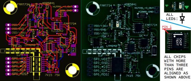
All LEDs are aligned cathode down, and all chips with 6 or more pins are aligned with pin 1 in the top left, in the view shown above. Everything else's alignment is either obvious (3 pins and only fits one way) or doesn't matter (resistors and nonpolarized ceramic capacitors). I designed this board with ease of building in mind.
[ -- Used in step -- ]
Temperature controlled soldering iron (recommendation for Sn/Pb solder: set to 320 C for soldering, 375 C for desoldering with the desoldering braid)
Flux pen
Desoldering braid
Tweezers
60/40 or 63/37 Sn/Pb solder, fine diameter, rosin core
Circuit boards and tiny components previously ordered from Mouser and Seeed
[ -- Procedure -- ]
Your soldering process for multipin surface mount chips will look like this:
1. Use flux pen to coat pads on board
2. Blob solder on a corner pad
3. Grab chip with tweezers and align on circuit board pads while holding iron tip to the corner pad that got extra solder
4. Remove soldering iron tip, check chip/pad alignment, GOTO 3 if chip is misaligned
5. Melt solder into the general vicinity of the pins/pads. Some pins will probably be bridged.
6. Raise iron temperature, remove solder bridges with desoldering braid
7. Reexamine solder joints for bridging, GOTO 5 if bridged (adding a little solder to a bridge so it's convex makes it easier to remove with the desoldering braid)
================================
ASSEMBLING THE DEVICE
================================
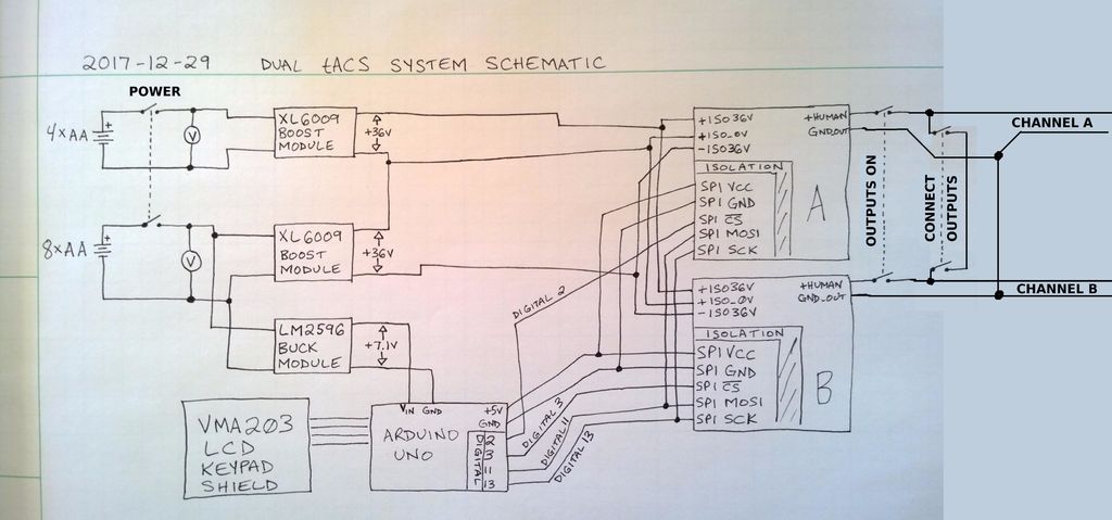
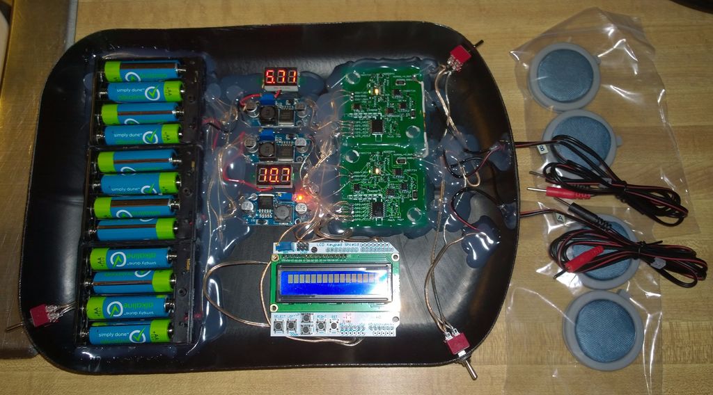
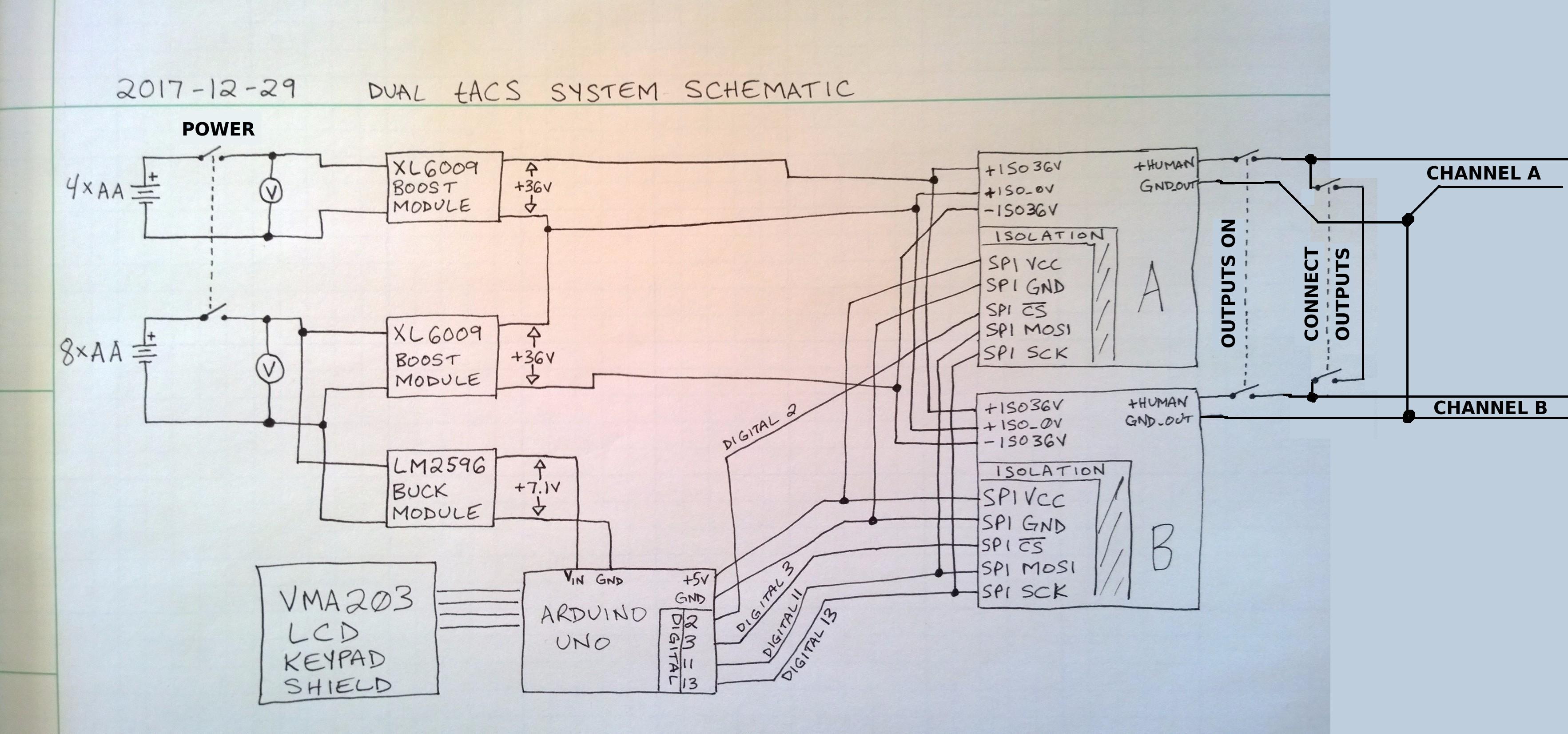
Begin by attaching two of the battery holders in series. The larger, 8-cell battery will ultimately power the Arduino and screen. Both the 8-cell and 4-cell batteries must have their positive output leads first routed through the power switch and then connected to panel voltmeters. The batteries should be replaced when there is less than 1v per cell.
The 4-cell battery powers only a single XL6009 boost module whose output must be set to 36V.
The 8-cell battery powers two modules, an XL6009 boost module whose output must be set to 36V, and an LM2596 buck module whose output must be set to 7.1V.
The two XL6009 boost modules' outputs are wired in series, with the center point being connected to ISO_+0V on each tACS circuit board, and the endpoints connected to ISO_+36V and ISO_-36V on each tACS circuit board.
The LM2596 buck module's 7.1V output goes to Vin on the Arduino Uno, into which the VMA203 keypad/screen module is plugged.
The Arduino's +5v output and GND are connected to each tACS board's +SPI_VCC and +SPI_GND terminals.
The Arduino's digital 11 output should be wired to SPI_MOSI of both tACS boards, the Arduino's digital 13 output should be wired to the SPI_SCK of both boards. Arduino digital 2 is connected to Channel A board's SPI_*CS, Arduino digital 3 is connected Channel B board's SPI_*CS.
The +HUMAN_I_OUT terminals of each board must be routed through a DPDT switch which may disconnect them from the output, and then past another switch which may short them together if desired, before being connected to the red wires of the output electrode leads. The +HUMAN_GND_OUT terminals of each board are connected together (though they already are through the power supply, note that severing this connection will not electrically disconnect the device grounds), then connected to the black wires of the output electrode leads.
================================
Using the Interface
================================
The device has three switches:
Power on / off:
Turns the device on or off.
Outputs on / off:
Turns the outputs on or off.
Outputs connected / separate:
Electrically connects both signal (red) lines. Used to connect both channel outputs to a single signal electrode, superimposing the channels' outputs.
----
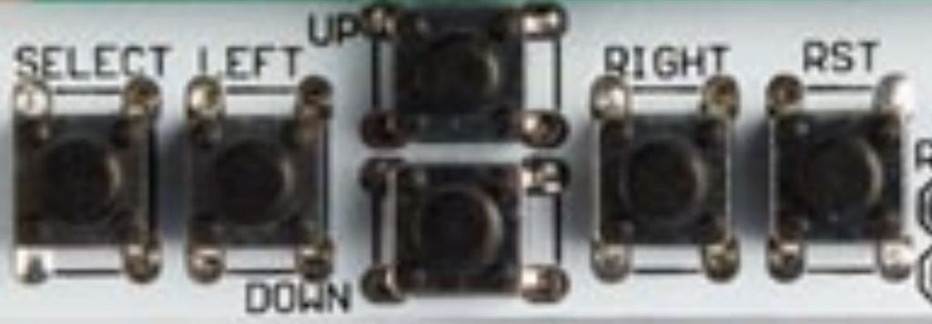
The interface screen has six buttons under it:
RST:
Resets the entire device.
SELECT:
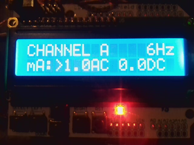
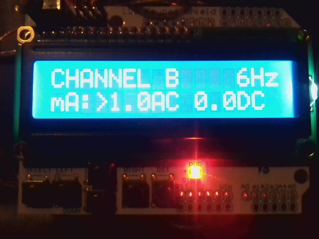
Cycles through the three screens, Channel A, Channel B, and Mode.
LEFT:
Cycles the pointer ( ">" or "<" ) through the fields on the current screen. The pointer indicates which field can be changed by the UP or DOWN keys. On some mode screens, this pointer can disappear from view, but it can be found again by pressing LEFT or RIGHT repeatedly.
RIGHT:
Cycles the pointer ( ">" or "<" ) through the fields on the current screen. The pointer indicates which field can be changed by the UP or DOWN keys. On some mode screens, this pointer can disappear from view, but it can be found again by pressing LEFT or RIGHT repeatedly.
UP:
If pressed once, increases by one the field indicated by ">" or "<". If held down, rapidly increases the field indicated by ">" or "<".
DOWN:
If pressed once, decreases by one the field indicated by ">" or "<". If held down, rapidly decreases the field indicated by ">" or "<".
================================
Software Operation, Normal Mode
================================
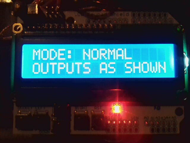
In normal mode, both channels are always on at the set frequencies, amplitudes, and offsets.
Normal mode is used to replicate the following montages:
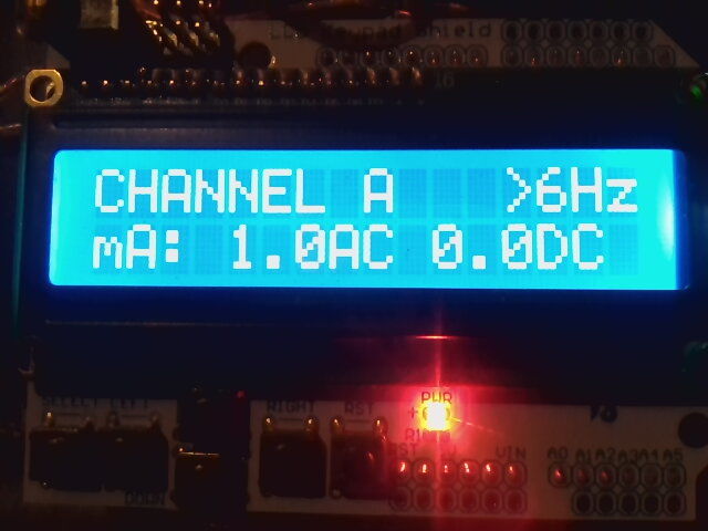
Single-Frequency Alternating Current Stimulation: SF-6
A continuous, sinusoidal 6 Hz stimulation was applied at an intensity of 1 mA peak to baseline.
---
For single-frequency alternating current stimulation, the "channel
connect" switch should be set to DISCONNECT THE OUTPUTS,
and only channel A needs to be connected to output electrodes.
Channel A should be set to 6Hz, 1.0mA AC, 0.0mA DC.
--
Single-channel theta frequency (5Hz) stimulation
Stimulation waveform was sinusoidal without DC offset and a 0° relative phase. Current intensity was 1500 μA.
{editor's note: how do you have "relative phase" with
only one channel?
relative to what? This part of these
published methods I did not know how to replicate.}
---
For single-channel theta frequency (5Hz) stimulation, the "channel connect" switch should be set to DISCONNECT THE OUTPUTS, and only channel A needs to be connected to output electrodes. Channel A should be set to 5Hz, 1.5mA AC, 0.0mA DC.
================================
Software Operation, Bursts Mode
================================
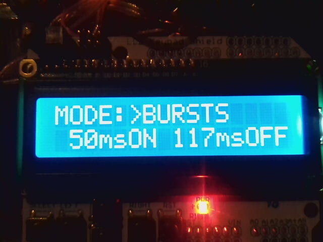
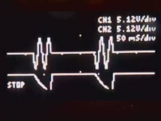
In bursts mode, both channels turn on for msON milliseconds, then off for msOFF milliseconds. The burst frequency is 1000/(msON+msOFF), or 6Hz for the values shown, 50ms and 117ms.
Bursts mode is used to replicate the following stimulation montage:
Gamma-Burst Stimulation: Bursts
Bursts of 80 Hz alternating current were applied for 50 ms six times per s with a current of 0.4 mA peak to baseline with positive or negative DC offset (Bursts+ or Bursts−). Total intensity was equal to 1 mA peak to baseline. These stimulation conditions were designed to reproduce the conditions CF-6,80t and CF-6,80p without the continuous slow-wave component.
Only channel A needs to be connected to electrodes to replicate this montage. Channel B should be left disconnected, and the "connect channels" switch must be set to CHANNELS SEPARATE. The device should be set to BURSTS mode, and channel A must be set to the following: 80Hz, 0.4mA AC, and 0.6mA DC for Bursts+, or -0.6mA DC for Bursts-.
================================
Software Operation, Phase Set Mode
================================
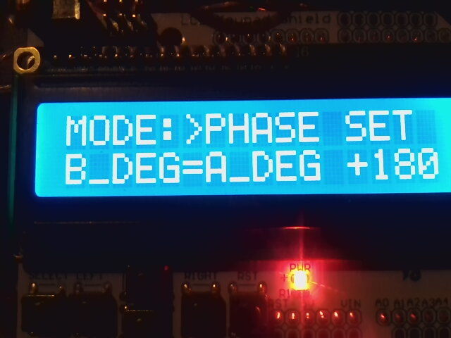
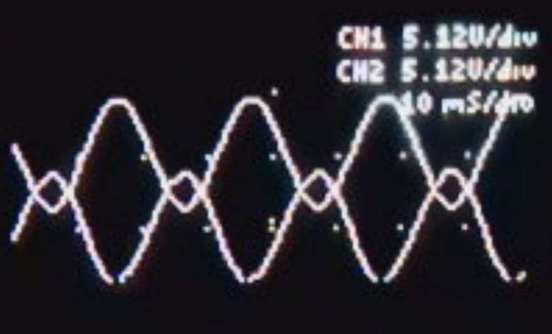
In phase set mode, the frequency of channel B is forced to be the same as the frequency of channel A. The phase relationship is set such that the outputs' values are given by the functions:
Channel A = AmplitudeA*sin(A_degrees) + OffsetA
Channel B = AmplitudeB*sin(A_degrees + PHASE_SHIFT) + OffsetB
Phase set mode is used to replicate the following stimulation montage:
In- and anti-phase theta frequency (6 Hz) stimulation
Stimulation was sinusoidal, 6 Hz frequency, peak-to-peak amplitude of 1000 μA, and no DC offset. TACS was delivered in two different conditions: (1) Synchronous condition (0°) - Electrodes F4 and P4 with a 0° phase offset and return electrode at T8; (2) Desynchronous condition (180°) - same montage as in the ‘synchronous’ condition, but electrodes F4 and P4 had a 180° phase offset.
Both channels need to be connected to electrodes to replicate this montage. The "connect channels" switch must be set to CHANNELS SEPARATE. The device should be set to PHASE SET mode, and channel A must be set to the following: 6Hz, 1.0mA AC, 0.0mA DC. Channel B must be set to 1.0mA AC, 0.0mA DC (its frequency will automatically be set to match channel A). Within the MODE:PHASE SET screen, B_DEG=A_DEG must be +180 for desynchronous condition, and 0 for synchronous condition.
================================
Software Operation, Cross-Frequency Mode
================================
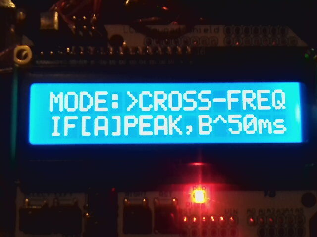
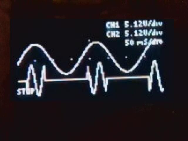
Channel A is always on, but channel B is only turned on during channel A's Peak or Trough (user set). Channel B is turned on for 50ms in the setup shown. Channel B's on-time can be changed from the 50ms value through the user interface if desired.
Phase set mode is used to replicate the following stimulation montage:
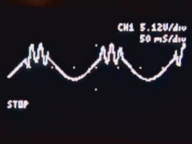
Cross-Frequency Alternating Current Stimulation: CF-“Theta-Gamma Frequencies”
This stimulation consisted of two superimposed components: continuous slow wave, and repetitive bursts of fast oscillations. The slow component was the 6 Hz sinusoidal stimulation with 0.6-mA peak-to-baseline current for every corresponding condition. The fast component frequency was 40 Hz (condition CF-6,40t), 80 Hz (CF-6,80t and CF-6,80p), 100 Hz (CF-6,100p), 140 Hz (CF-6,140p), or 200 Hz (CF-6,200p) at 0.4 mA peak to baseline. Bursts were synchronized with the continuous wave and lasted for 50 ms during every trough (CF-6,80t) or peak (CF-6,40p, CF-6,80p, CF-6,100p, CF-6,140p, and CF-6,200p).
Only one channel needs to be connected to electrodes to duplicate this montage. The "connect outputs" switch should be set to OUTPUTS CONNECTED. MODE should be set to CROSS-FREQ, PEAK or TROU as desired, 50ms. Channel A should be set to 6Hz, 0.6mA AC, 0.0mA DC. Channel B should be set to 0.4mA AC, 0.0mA DC, and 40, 80, 100, 140, or 200 Hz as desired.